|
Example
3. User-defined Laser Beam Profile
In
this example the quadrilayer stack is illuminated by a user-defined laser
beam profile incident from the surface side.
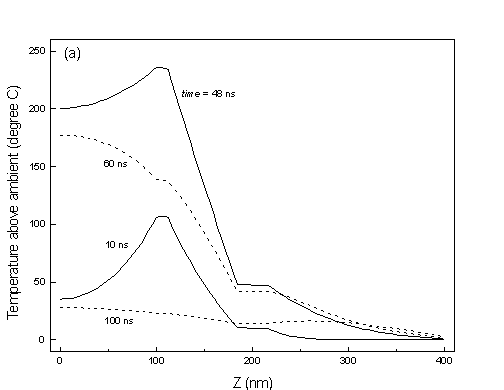
Calculated
profiles of temperature versus z are shown in Figure�(a), and isotherms
in the XY-plane at z�=�108�nm appear in Fig.�(b).
Shown
below is the file TR03.SYS, which contains the structural parameters of
the multilayer stack, the laser beam profile, and the chosen mesh parameters.
!@@@@@@@@@@@@@@@@@@@@@@@@@@@@@@@@@@@@@@@@@@@@@@@@@@@@@@@@@@@@@@@@@@@@@@@@@#
!                  @@ TEMPROFILE 5.0     File TR03.SYS @@                 #
!                  @@ Date: 01/01/1999     Time: 13:18 @@                 #
!                  @@@@@@@@@@@@@@@@@@@@@@@@@@@@@@@@@@@@@@                 #
!                                                                         #
! Notes:  Quadrilayer stack used in Test Run 3. The incident beam profile #
!         is user-defined.                                                #
!                                                                         #
!!!!!!!!!!!!!!!!!!!!!!!!!!!!!!!!!!!!!!!!!!!!!!!!!!!!!!!!!!!!!!!!!!!!!!!!!!#
$                                                                         #
    Top/Bottom incidence: T                                               #
$                                                                         #
 Substrate's index (n,k):    1.4600000       .00000000                    #
 Thermal constants (C,K):    1.7000000      2.00000000E-03                #
$                                                                         #
        Number of layers:  4                                              #
$                                                                         #
Layer 01:  Thickness,n,k:    32.000000       1.2000000       6.9000000    #
                     C,K:    2.7000000       2.4000000                    #
$                                                                         #
Layer 02:  Thickness,n,k:    72.000000       1.5000000       .00000000    #
                     C,K:    2.0000000      1.50000000E-02                #
$                                                                         #
Layer 03:  Thickness,n,k:    12.000000       3.1000000       3.5000000    #
                     C,K:    2.6000000       .16000000                    #
$                                                                         #
Layer 04:  Thickness,n,k:    100.00000       1.5000000       .00000000    #
                     C,K:    2.0000000      1.50000000E-02                #
$                                                                         #
Heat loss factor (GAMMA):    .00000000                                    #
$                                                                         #
   Incident Beam Profile: User-defined                                    #
               LAMBDA,RS:    632.80000       1000.0000                    #
  Point on profile (r,I):    .00000000       1.0000000                    #
  Point on profile (r,I):    50.000000       .97260000                    #
  Point on profile (r,I):    100.00000       .89480000                    #
  Point on profile (r,I):    150.00000       .77880000                    #
  Point on profile (r,I):    200.00000       .64120000                    #
  Point on profile (r,I):    250.00000       .49940000                    #
  Point on profile (r,I):    300.00000       .36790000                    #
  Point on profile (r,I):    350.00000       .25640000                    #
  Point on profile (r,I):    400.00000       .16900000                    #
  Point on profile (r,I):    450.00000       .10540000                    #
  Point on profile (r,I):    500.00000      6.22000000E-02                #
  Point on profile (r,I):    550.00000      3.47000000E-02                #
  Point on profile (r,I):    600.00000      1.83000000E-02                #
  Point on profile (r,I):    650.00000      9.10000000E-03                #
  Point on profile (r,I):    700.00000      4.30000000E-03                #
  Point on profile (r,I):    750.00000      1.90000000E-03                #
  Point on profile (r,I):    800.00000      8.00000000E-04                #
  Point on profile (r,I):    850.00000      3.00000000E-04                #
  Point on profile (r,I):    900.00000      1.00000000E-04                #
  Point on profile (r,I):    1000.0000       .00000000                    #
Impulse: POWER,TAU,NSTEP:    3.0000000       1.0000000             5      #
$                                                                         #
Mesh:         RMAX,DLTAR:    2000.0000       25.000000                    #
              ZMAX,DLTAZ:    400.00000       4.0000000                    #
                    TMAX:    100.00000                                    #
!@@@@@@@@@@@@@@@@@@@@@@@@@@@@@@@@@@@@@@@@@@@@@@@@@@@@@@@@@@@@@@@@@@@@@@@@@#
|
Shown
below is the file GSSN.RIP, which contains the radial intensity profile
(RIP) of the user-defined incident beam in Example 3. The user can modify
the contents of this file with a text editor, then import it to the program
environment during subsequent runs of TEMPROFILE.
!@@@@@@@@@@@@@@@@@@@@@@@@@@@@@@@@@@@@@@@@@@@@@@@@@@@@@@@@@@@@@@@@@@@@@@@@@#
!                  @@ TEMPROFILE 5.0     File GSSN.RIP @@                 #
!                  @@ Date: 12/26/1998     Time: 12:04 @@                 #
!                  @@@@@@@@@@@@@@@@@@@@@@@@@@@@@@@@@@@@@@                 #
!                                                                         #
! Notes: Gaussian intensity distribution with 1/e radius R0=300nm.        #
!                                                                         #
!!!!!!!!!!!!!!!!!!!!!!!!!!!!!!!!!!!!!!!!!!!!!!!!!!!!!!!!!!!!!!!!!!!!!!!!!!#
  Point on profile (r,I):    .00000000       1.0000000                    #
  Point on profile (r,I):    50.000000       0.9726000                    #
  Point on profile (r,I):    100.00000       0.8948000                    #
  Point on profile (r,I):    150.00000       0.7788000                    #
  Point on profile (r,I):    200.00000       0.6412000                    #
  Point on profile (r,I):    250.00000       0.4994000                    #
  Point on profile (r,I):    300.00000       0.3679000                    #
  Point on profile (r,I):    350.00000       0.2564000                    #
  Point on profile (r,I):    400.00000       0.1690000                    #
  Point on profile (r,I):    450.00000       0.1054000                    #
  Point on profile (r,I):    500.00000       0.0622000                    #
  Point on profile (r,I):    550.00000       0.0347000                    #
  Point on profile (r,I):    600.00000       0.0183000                    #
  Point on profile (r,I):    650.00000       0.0091000                    #
  Point on profile (r,I):    700.00000       0.0043000                    #
  Point on profile (r,I):    750.00000       0.0019000                    #
  Point on profile (r,I):    800.00000       0.0008000                    #
  Point on profile (r,I):    850.00000       0.0003000                    #
  Point on profile (r,I):    900.00000       0.0001000                    #
  Point on profile (r,I):    1000.0000       0.0000000                    #
!@@@@@@@@@@@@@@@@@@@@@@@@@@@@@@@@@@@@@@@@@@@@@@@@@@@@@@@@@@@@@@@@@@@@@@@@@#
|
The
file TR03.PLS shown below was created in Example 3, and contains the laser
pulse shape. Pairs of points (t,�P) at the corners of the piecewise linear
function P(t), initially entered from the keyboard, are saved in this
file.
    !@@@@@@@@@@@@@@@@@@@@@@@@@@@@@@@@@@@@@@@@@@@@@@@@@@@@@@@@@@@@@@@@@@@@@@@@@#
    !                  @@ TEMPROFILE 5.0     File TR01.PLS @@                 #
    !                  @@ Date: 12/31/1998     Time: 18:34 @@                 #
    !                  @@@@@@@@@@@@@@@@@@@@@@@@@@@@@@@@@@@@@@                 #
    !                                                                         #
    ! Notes: Trapezoidal pulse shape of the laser beam. The rise and fall     #
    !        times are 10 nsec each, and the total pulse width is 60 nsec.    #
    !                                                                         #
    !!!!!!!!!!!!!!!!!!!!!!!!!!!!!!!!!!!!!!!!!!!!!!!!!!!!!!!!!!!!!!!!!!!!!!!!!!#
        Point on pulse (t,P):    10.000000       2.0000000                    #
        Point on pulse (t,P):    50.000000       2.0000000                    #
        Point on pulse (t,P):    60.000000       .00000000                    #
        Point on pulse (t,P):    100.00000       .00000000                    #
    !@@@@@@@@@@@@@@@@@@@@@@@@@@@@@@@@@@@@@@@@@@@@@@@@@@@@@@@@@@@@@@@@@@@@@@@@@#
|
(a)
Profiles of temperature versus z at (x,�y) = (0,�0) computed at several
instants of time.
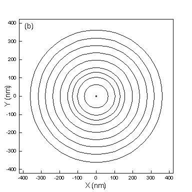
(b)
Isotherms in the XY-plane at z�=�108�nm, time�=�50�ns. The hottest spot
at the center has temperature T�=�237.15�C (above ambient). The plotted
isotherms, starting in the middle and moving outward, correspond to T�=�237�C,
230�C, 220�C, 210�C, 200�C, 180�C, 160�C, 140�C, 120�C, and 100�C.

Home
| About MM Research, Inc. | Online
Publications
Diffract
| SIM 3D_Max | Multilayer
| Temprofile

© Copyright
1987-2011, MM Research, Inc.
5748 N. Camino del Conde, Tucson, Arizona 85718
|